Troubleshooting digital signals and protocols such as Serial Peripheral Interface (SPI) and Inter-Integrated Circuit (I2C) can be notoriously difficult. The SPI protocol is particularly tricky due to the fact that it is loosely specified with a wide range of implementations. It’s exceedingly helpful to use a logic analyzer when troubleshooting, but what happens when your analyzer is apparently leading you astray!
In this post I’ll document the case of the unruly SPI chip select (CS) signal, how it interfered with my troubleshooting, and how I fixed it. If you’re a grizzled old veteran of digital signal electronics and analyzers none of this is going to come as a surprise, but if you’re a neophyte and have just started out with a logic analyzer, hopefully you’ll learn something and save yourself some head scratching.
The Hardware
Many years ago I worked on a project collecting vibration sensor data and storing it to a Microchip 23A256 SRAM chip. Knowing that the SPI interface to the chip was straightforward I set out to use one with an Arduino Uno, but given its lower voltage requirements (1.95V maximum), I ordered up a handful of 23LC512s (2.5V minimum, 5.5V maximum). Altogether the hardware involved here is:
- an Arduino Uno
- one 23LC512 Serial SRAM
- a Saleae Logic 8 logic analyzer
You will note that the 23LC512 also supports what are referred to as SDI and SQI mode. We are using neither in this example.
Wiring up the 23LC512
Wiring up the 23LC512 to the Arduino is a piece of cake, and requires little more than connecting the signal pins, VCC, and VSS (GND). A technical note does recommend using a 0.1 uF decoupling capacitor on VCC, so we’ll do that. As the Arduino is always driving the CS line we’ll skip adding a pull-up resistor on it.
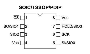
23LC512 pins:
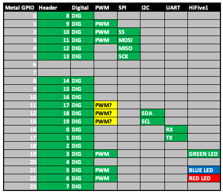
Mapping pins from the Arduino to the 23LC512:

Communicating With the 23LC512
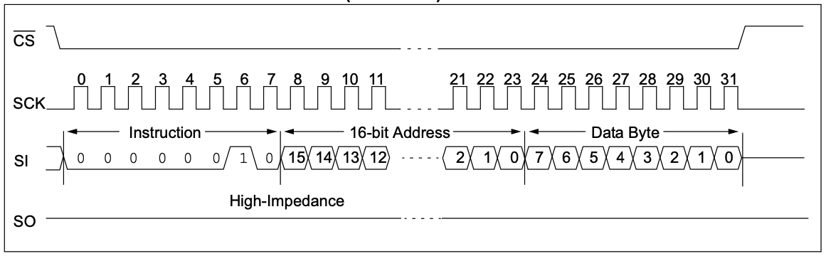
Writing to the 23LC512 is straightforward using the Arduino SPI library. The datasheet is clear as well. The device uses an active low chip select, so all one needs to do is:
- lower the CS line
- transmit the 23LC512 write command, which is encoded as
b0000 0010(0x02), to the SI pin - transmit the 16-bit address you want to write to the SI pin
- transmit the byte you want to write to the SI pin
- raise the CS line
In code this looks like:
|
1 2 3 4 5 6 7 8 9 10 11 12 13 14 15 16 17 18 19 20 21 |
#include <SPI.h> const uint8_t CS = 10; // Microchip 512Kbit SPI Serial SRAM with SDI and SQI Interface // https://ww1.microchip.com/downloads/en/DeviceDoc/20005155B.pdf const uint8_t SRAM_WRITE_CMD = 0x02; const uint8_t SRAM_READ_CMD = 0x03; // Write data to the given address void sram_write(const uint16_t address, const uint8_t data) { digitalWrite(CS, LOW); // Select SRAM chip SPI.transfer(SRAM_WRITE_CMD); SPI.transfer16(address); SPI.transfer(data); digitalWrite(CS, HIGH); // Deselect SRAM chip } |
Honestly, in the world of communicating with a chip, it doesn’t get much easier than that.
Let’s round things out with the read command, which looks like this:
|
1 2 3 4 5 6 7 8 9 10 11 12 13 |
// Read data from the given address uint8_t sram_read(const uint16_t address) { digitalWrite(CS, LOW); SPI.transfer(SRAM_READ_CMD); SPI.transfer16(address); const uint8_t rx = SPI.transfer(0); digitalWrite(CS, HIGH); return rx; } |
And now a loop which just writes and reads bytes to random addresses:
|
1 2 3 4 5 6 7 8 9 10 11 12 13 14 15 16 17 18 19 20 21 22 23 24 |
void setup() { Serial.begin(9600); SPI.begin(); } char message[256]; void loop() { uint16_t addr = random(65535); uint8_t data_w = random(255); sprintf(message, "Writing %x to %x", data_w, addr); Serial.println(message); sram_write(addr, data_w); delay(1000); uint8_t rx = sram_read(addr); sprintf(message, "Read %x from %x", rx, addr); Serial.println(message); delay(1000); } |
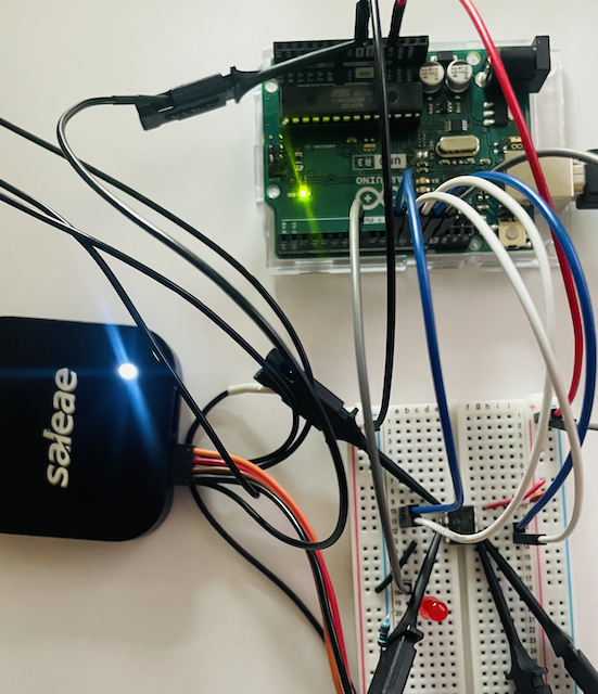
Hooking Up the Logic Analyzer
I cannot recommend the Saleae logic analyzers enough. While a bit pricy, they and the Logic 2 software are quite easy to use. Here I’ve connected up the CS, SI, SO, and SCK lines, and a ground.
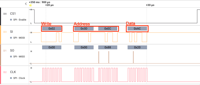
Now, while the code was working fine, and indeed, the chip itself was working fine (data could be written and read), the logic analyzer was showing the CS line bouncing high.
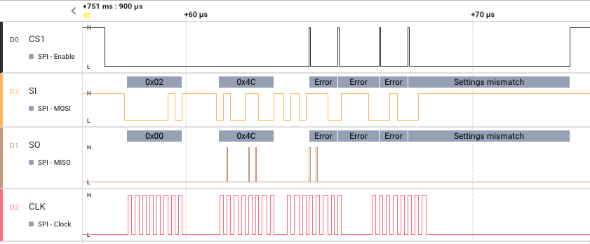
Now, since the chip is working, one might ask what the big deal is, but if there is noise you can see that it throws the protocol analyzer off. Take a look again:
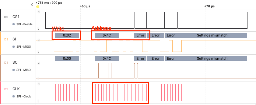
The first byte out after CS went low is the Write command for the 23LC512, followed by the address. But notice that after the upper byte of the address is displayed that CS line is read as high, thus confusing the protocol analyzer. In other words, the protocol analyzer believes CS was high, which causes the rest of this transaction to appear “garbled.” Well that’s no good, so let’s fix it.
The answer (as usual) was in the manual all along! When dealing with high speed interfaces you should connect a ground for each signal.
The Arduino ICSP header has a ground pin located at the edge of the board so it made sense to connect the additional logic analyzer grounds there.
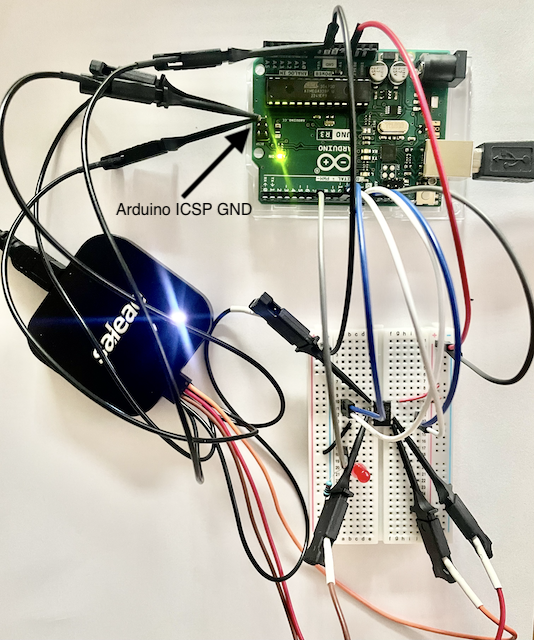
Now that we’ve connected a ground pin for each signal line, we run again and get a nice clean CS reading and can decode the full transaction.