A few years back I purchased a SiFive HiFive1 Rev B board to join in the RISC-V revolution.
In this post we’ll look at using the HiFive to communicate with a Microchip 23LC512 SRAM via SPI. I’m fond of these chips because they support up to 5V and are easy to communicate with. Moreover, writing data and reading it back is a nice way of confirming your communications are working!
Zephyr
Zephyr is a scalable real-time operating system with permissive licensing (Apache). It is supported on the HiFive1, alongside Freedom Metal and FreeRTOS. Sure, we could have chosen to use Freedom Metal or FreeRTOS, but Zephyr provides a solid foundation upon which to build RTOS applications on a RISC-V platform.
Wiring it Up
SiFive built the HiFive1 Rev B to be “pin compatible” with the Arduino, and markets it as such. If you’ve used SPI on a board like the Arduino Uno you’ll recognize the following SPI pin assignments:
- CS – Pin 10
- SO – Pin 11
- SI – Pin 12
- CLK – Pin 13
The HiFive1 schematics shows that it uses these same pins for the SPI1 controller.

PlatformIO and Zephyr
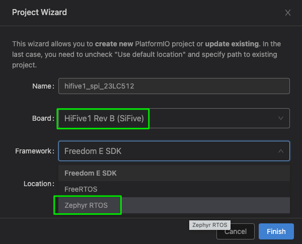
We’ve used PlatformIO with Visual Studio Code in the past, and will use it here as well. Create a new project with PlatformIO:

For our board, we’ll choose the HiFive1 Rev B (SiFive) and for the Framework choose Zephyr RTOS.
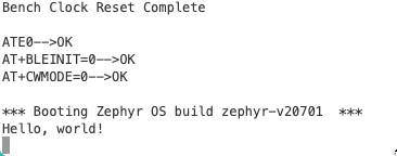
First, some basic code to ensure we can flash the HiFive1 Rev B and boot into Zephyr.
|
1 2 3 4 5 6 7 8 |
#include <zephyr.h> #include <stdio.h> void main(void) { printf("Hello, world!\n"); } |
Now, to the fun stuff.
Like Linux, Zephyr uses the device tree to describe hardware peripherals. Unlike Linux, obtaining a handle to a device uses a quite sophisticated set of preprocessor macros. I highly recommend this presentation for an explanation on how the macros work.
Armed with this knowledge, let’s get a SPI device structure.
|
1 2 3 4 5 6 7 8 9 10 11 12 13 14 15 16 17 18 19 20 21 22 |
#include <zephyr.h> #include <stdio.h> #include <device.h> #include <devicetree.h> #include <drivers/spi.h> const struct device* spi_device; struct spi_config spi_device_config; int main(void) { spi_device = DEVICE_DT_GET(DT_NODELABEL(spi1)); if (!spi_device) { printf("Unable to obtain SPI device\n"); return -1; } return 0; } |
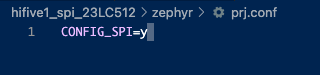
Unfortunately if you tried to compile this as-is you will likely end up with a linker error saying something like undefined reference to __device_dts_ord_30.
To fix this error we need to enable SPI support in a file called prj.conf. This file is merged together with Zephy’s KConfig. In your PlatformIO project folder, prj.conf should go in the zephyr/ directory.
Compile again and upload the firmware to the HiFive1 and you shouldn’t see Unable to obtain SPI device because you’ll have a valid handle. Let’s continue and build up our SPI configuration.
[code lang=text]
spi_device_config.frequency = SPI_FREQUENCY; // 20000000 (20MHz)
spi_device_config.operation = SPI_OP_MODE_MASTER | SPI_WORD_SET(8);
[/code]
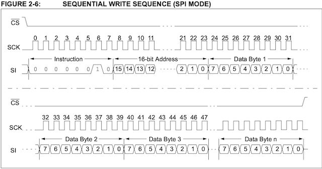
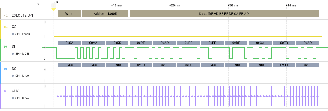
With that completed, the tricky part! We’re going to write the function that allows us to write a set of sequential bytes to the SRAM. To do so requires an understanding of the SPI protocol specific to the 23LC512 chip, and to gain that understanding look at the datasheet. After doing so, you’ll know to write a stream of bytes we first transmit the Write command (0x02), followed by a 16-bit address, followed by as many bytes as we want to write. All the while the chip select line needs to be held low. Again, this is made clear by the datasheet:
Let’s accomplish this in C with our Zephyr SPI API. First, the code, and then the explanation.
|
1 2 3 4 5 6 7 8 9 10 11 12 13 14 15 16 17 18 19 20 21 22 23 24 25 26 |
#define WRITE_INS 0x02 void sram_write(uint16_t address, uint8_t* data, uint8_t len) { uint8_t addr_h = address >> 8; uint8_t addr_l = address & 0xff; uint8_t writeInst[] = {WRITE_INS, addr_h, addr_l}; struct spi_buf tx_buffers[] = { { .buf = (void*)writeInst, .len = 3 }, { .buf = data, .len = len } }; struct spi_buf_set tx_buffer_set = { .buffers = tx_buffers, .count = 2 }; spi_write(spi_device, &spi_device_config, &tx_buffer_set); } |
Four C structures are required to write a SPI transaction with Zephyr:
struct devicestruct spi_configstruct spi_bufstruct spi_buf_set
Our first structure, device, is the SPI device itself. The second, spi_config, holds configuration data specific to our SPI transaction. For example, what frequency are we using, is it MSB-first or LSB-first, etc.
The third and fourth structures package up the data we’re going to send. It’s worth reviewing this a couple of times. The complete SPI transaction will be in our buffer set. That buffer set is a list of buffers we want to write.
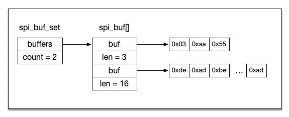
Once we’ve constructed our buffers and buffer set, we can write our data out in a single transaction with spi_write.
If you’re familiar with SPI you know that when you write data to SI, you’ll get data back on SO. This will be important when we attempt to read back in what we’ve written.
Generating Random Data
To test and gain confidence that our write and read functions are working properly we’ll generate random data to write to the SRAM. To do so we need to enable a test random number generator. In your prj.conf file add CONFIG_TEST_RANDOM_GENERATOR=y, which will allow us to write code like this:
[code lang=text]
#include <random/rand32.h>
uint32_t r = sys_rand32_get();
[/code]
Reading from the SRAM
Reading from the SRAM requires a bit more complexity in our spi_buf and spi_buf_set structures. First, the code, and then the explanation (of why it won’t work!).
|
1 2 3 4 5 6 7 8 9 10 11 12 13 14 15 16 17 18 19 20 21 22 23 24 25 26 27 28 29 30 |
#define READ_INS 0x03 void sram_read(uint16_t address, uint8_t* data, uint8_t len) { uint8_t addr_h = address >> 8; uint8_t addr_l = address & 0xff; uint8_t readInst[] = {READ_INS, addr_h, addr_l}; struct spi_buf tx_buffer = { .buf = (void*)readInst, .len = 3 }; struct spi_buf rx_buffer= { .buf = (void*)data, .len = len }; const struct spi_buf_set tx_buf_set = { .buffers = (const struct spi_buf*)&tx_buffer, .count = 1 }; const struct spi_buf_set rx_buf_set = { .buffers = (const struct spi_buf*)&rx_buffer, .count = 1 }; spi_transceive(spi_device, &spi_device_config, &tx_buf_set, &rx_buf_set); } |
While this looks like it would work, and our logic analyzer is able to interpret the data, here’s what we see in the console:
[code lang=text]
Write 0x07c4: d1 d4 d7 da dd e1 e4 e7 ea ed f0 f3 f7 fa fd 00
Read 0x07c4: 00 00 00 d1 d4 d7 da dd e1 e4 e7 ea ed f0 f3 f7
Write 0x959d: a0 a3 a6 aa ad b0 b3 b6 b9 bc c0 c3 c6 c9 cc cf
Read 0x959d: 00 00 00 a0 a3 a6 aa ad b0 b3 b6 b9 bc c0 c3 c6
[/code]
The first three bytes of our read buffer is zeros, and the last three bytes that were written are missing. Recall once again that SPI transactions are “write-a-byte-read-a-byte”. To read a byte we must transmit a byte. In the code above we have a mismatch of transmitting 3 bytes (thereby reading three bytes into our read buffer). To resolve this we’ll ensure that our transmit and receive buffers are of the same size.
|
1 2 3 4 5 6 7 8 9 10 11 12 13 14 15 16 17 18 19 20 21 22 23 24 25 26 27 28 29 30 31 32 33 34 |
#define READ_INS 0x03 void sram_read(uint16_t address, uint8_t* data, uint8_t len) { uint8_t addr_h = address >> 8; uint8_t addr_l = address & 0xff; uint8_t readInst[] = {READ_INS, addr_h, addr_l}; struct spi_buf tx_buffers[] = {{ .buf = readInst, .len = 3} ,{ .buf = NULL, .len = len }}; struct spi_buf rx_buffers[] = {{ .buf = NULL, .len = 3}, { .buf = (void*)data, .len = len }}; const struct spi_buf_set tx_buf_set = { .buffers = (const struct spi_buf*)&tx_buffers, .count = 2 }; const struct spi_buf_set rx_buf_set = { .buffers = (const struct spi_buf*)&rx_buffers, .count = 2 }; spi_transceive(spi_device, &spi_device_config, &tx_buf_set, &rx_buf_set); } |
We now see:
[code lang=text]
Write 0xb44e: 51 54 57 5b 5e 61 64 67 6a 6d 71 74 77 7a 7d 80
Read 0xb44e: 51 54 57 5b 5e 61 64 67 6a 6d 71 74 77 7a 7d 80
Write 0x3883: 86 89 8c 90 93 96 99 9c 9f a2 a5 a9 ac af b2 b5
Read 0x3883: 86 89 8c 90 93 96 99 9c 9f a2 a5 a9 ac af b2 b5
[/code]
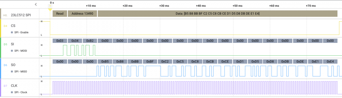
So, what’s going on here? Notice that our transmit buffers and receive buffers are now the same size. Three bytes are transmitted while three bytes are read in. It just so happens that the three bytes read in will be discarded, but we then transmit out len bytes (of zeros), while reading in len bytes of data from the SI line.
An example of what we see with a logic analyzer:
The Code
Now, for the complete code:
|
1 2 3 4 5 6 7 8 9 10 11 12 13 14 15 16 17 18 19 20 21 22 23 24 25 26 27 28 29 30 31 32 33 34 35 36 37 38 39 40 41 42 43 44 45 46 47 48 49 50 51 52 53 54 55 56 57 58 59 60 61 62 63 64 65 66 67 68 69 70 71 72 73 74 75 76 77 78 79 80 81 82 83 84 85 86 87 88 89 90 91 92 93 94 95 96 97 98 99 100 101 102 103 104 105 106 107 108 109 110 111 112 113 114 115 116 117 118 119 |
#include <zephyr.h> #include <stdio.h> #include <string.h> #include <device.h> #include <devicetree.h> #include <drivers/spi.h> #include <random/rand32.h> #define SPI_FREQUENCY 20000000 // 20 MHz const struct device* spi_device; struct spi_config spi_device_config; #define WRITE_INS 0x02 void sram_write(uint16_t address, uint8_t* data, uint8_t len) { uint8_t addr_h = address >> 8; uint8_t addr_l = address & 0xff; uint8_t writeInst[] = {WRITE_INS, addr_h, addr_l}; struct spi_buf tx_buffers[] = { { .buf = (void*)writeInst, .len = 3 }, { .buf = data, .len = len } }; struct spi_buf_set tx_buffer_set = { .buffers = tx_buffers, .count = 2 }; spi_write(spi_device, &spi_device_config, &tx_buffer_set); } #define READ_INS 0x03 void sram_read(uint16_t address, uint8_t* data, uint8_t len) { uint8_t addr_h = address >> 8; uint8_t addr_l = address & 0xff; uint8_t readInst[] = {READ_INS, addr_h, addr_l}; struct spi_buf tx_buffers[] = {{ .buf = readInst, .len = 3} ,{ .buf = NULL, .len = len }}; struct spi_buf rx_buffers[] = {{ .buf = NULL, .len = 3}, { .buf = (void*)data, .len = len }}; const struct spi_buf_set tx_buf_set = { .buffers = (const struct spi_buf*)&tx_buffers, .count = 2 }; const struct spi_buf_set rx_buf_set = { .buffers = (const struct spi_buf*)&rx_buffers, .count = 2 }; spi_transceive(spi_device, &spi_device_config, &tx_buf_set, &rx_buf_set); } #define BUFLEN 32 int main(void) { spi_device = DEVICE_DT_GET(DT_NODELABEL(spi1)); if (!spi_device) { printf("Unable to obtain SPI device\n"); return -1; } spi_device_config.frequency = SPI_FREQUENCY; spi_device_config.operation = SPI_OP_MODE_MASTER | SPI_WORD_SET(8); uint8_t tx_buf[BUFLEN]; uint8_t rx_buf[BUFLEN]; for (;;) { uint32_t addr = sys_rand32_get() & 0xffff; for (int i = 0; i < BUFLEN; i++) { tx_buf[i] = sys_rand32_get(); rx_buf[i] = 0x00; } sram_write(addr, tx_buf, BUFLEN); k_msleep(1000); sram_read(addr, rx_buf, BUFLEN); printf("Write 0x%04x: ", addr); for (int i = 0; i < BUFLEN; i++) { printf("%02x ", tx_buf[i]); } printf("\n"); printf("Read 0x%04x: ", addr); for (int i = 0; i < BUFLEN; i++) { printf("%02x ", rx_buf[i]); } printf("\n"); k_msleep(1000); } return 0; } |
Until Next Time
If you happen to end up using the 23LC512 SRAM and have a Salaea logic analyzer, check out our 23LC512 High Level Analyzer! It’s available in the Extensions of the Logic 2 software:
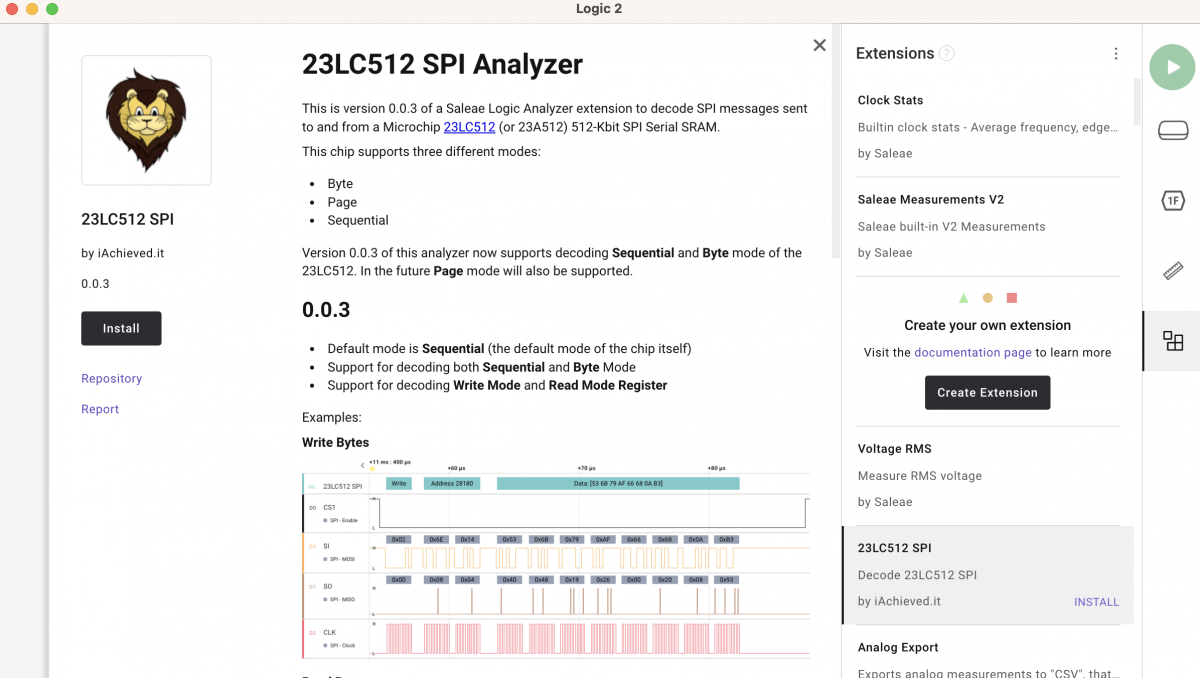
You can also find the source code for it on GitHub.
One thing I glossed over was the actual speed at which the SPI bus is running with the HiFive1 and Zephyr. Zooming in with the logic analyzer you can see that the clock frequency is definitely not 20 MHz, and is magnitudes of order slower.
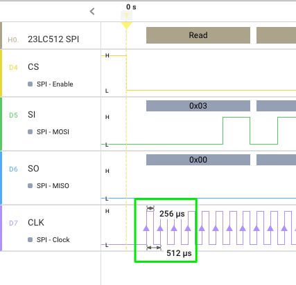
Reading a scant 16 bytes took 78 milliseconds.
Well, we can “fix that” by dropping our SPI frequency down to 100 kHZ. Yes.
[code lang=text]
#define SPI_FREQUENCY 100000
[/code]
Observing again a 16-byte transaction:

Ostensibly this slower SPI bus speed is due to the fact that the FE310 chip lacks DMA (directory memory access). I’m not certain at this point how to compensate for that to transmit data at faster rates to the SRAM, or if it is possible at all. Leave a comment if you have an idea!
