In my previous post I made mention that I could not use GPIO-based SPI chip selects on the BeagleBone Black with the default McSPI driver (what you are using if you’re opening /dev/spidev. The exact quote I had run across (much to my chagrin at the time) was
Incidentally, the spi-omap2-mcspi.c driver does not support a GPIO as a chip select.
Well, fortunately, a little persistence paid off (I confess, I can be stubborn at times), and I found this patch from Michael Welling that adds GPIO chip select support to the spi-omap2-mcspi.c driver.
As I mentioned in the article on using the 4-slot mikroBUS cape I was using a workaround to lower the chip select by hand. With Linux 4.3 and one additional patch you no longer need it. I’ve included everything in the BBB-420mA repository on the linux-4.3 branch, but wanted to share some additional tips for those looking to work with the cs-gpios tag in DTS files.
Declare your Pins
The snippet below cannot be taken out of context from the larger DTS overlay, but illustrates that we put our GPIO chip select pin in the same group as the rest of the SPI1 pins.
    bb_spi1_pins: pinmux_bb_spi1_pins {
    pinctrl-single,pins = <
      0x190 0x33    /* mcasp0_aclkx.spi1_sclk, INPUT_PULLUP | MODE3 */
      0x194 0x33    /* mcasp0_fsx.spi1_d0, INPUT_PULLUP | MODE3 */
      0x198 0x13    /* mcasp0_axr0.spi1_d1, OUTPUT_PULLUP | MODE3 */
      0x19c 0x13    /* mcasp0_ahclkr.spi1_cs0, OUTPUT_PULLUP | MODE3 */
      0x164 0x12    /* eCAP0_in_PWM0_out.spi1_cs1 OUTPUT_PULLUP | MODE2 */
      0x098 0x17    /* P8 10 gpio2_4.spi1_cs2 OUTPUT_PULLUP | MODE7 */
      >;
      };
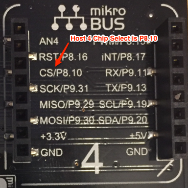
In particular the “magic” 0x098 0x17 refers to P8.10 on the Black (and actually the 0x098 refers to the pin and the 0x17 refers to the settings, which in this case we want OUTPUT_PULLUP and MODE7), which is gpio68 in /sys/class/gpio. Another name for it, which we’ll see below, is <&gpio2 4 0>. So many ways are referring to the same thing. No wonder it gets confusing.
Next, let’s revisit our DTS for SPI1 on the Black:
  fragment@1 {
    target = <&spi1>;   /* spi1 is numbered correctly */
    __overlay__ {
      status = "okay";
      pinctrl-names = "default";
      pinctrl-0 = <&bb_spi1_pins>;

#address-cells = <1>;
#size-cells = <0>;

      cs-gpios = <0>, <0>, <&gpio2 4 0>;

      spi1@0 {
#address-cells = <1>;
#size-cells = <0>;
    compatible = "spidev";
    reg = <0>;
    spi-max-frequency = <16000000>;
    spi-cpol;
    spi-cpha;
      };

      spi1@1 {
#address-cells = <1>;
#size-cells = <0>;
    compatible = "spidev";
    reg = <1>;
    spi-max-frequency = <16000000>;
    spi-cpol;
    spi-cpha;
      };

      spi1@2 {
#address-cells = <1>;
#size-cells = <0>;
    compatible = "spidev";
    reg = <2>;
    spi-max-frequency = <16000000>;
    spi-cpol;
    spi-cpha;
      };
    };
  };
The SPI bus documentation is a little unclear, but the format for the cs-gpios tag is:
cs-gpios = <GPIO>|<0>, <GPIO>|<0>, ..., <GPIO>|<0>;
where
- <0> means “use the default pin” for this chip select
- GPIO is expanded to something like
&gpio 4 0to identify the gpio pin
So in our example, the line
cs-gpios = <0>, <0>, <&gpio2 4 0>;
in the DTS overlay is telling the OMAP SPI driver that SPI1 chip select 0 (or CS0 you will see on the BeagleBone Black SPI pinouts) will use its default pin assignment, chip select 1 will also use its default pin assignment, and chip select 2 will use <&gpio2 4 0>, which as we said, is P8.10, aka GPIO 68. If you’re confused as to why I want to use P8.10, that’s because on the mikroBUS cape the clickboard in slot 4 has the chip select line running to P8.10 on the Black.
           CS0     CS1       CS2
         default default    P8.10
            |       |         |
            |       |         |
            v       v         v
cs-gpios = <0>,    <0>, <&gpio 2 4 0>;
See the GPIO overlay structure for details on the naming structure for GPIO pins, keeping in mind that “Exact meaning of each specifier cell is controller specific, and must be documented in the device tree binding for the device.” This is another way of saying that the structure of the GPIO names aren’t necessarily the same between the BeagleBone Black and say, a Raspberry Pi.
Get onto Linux 4.3
I want to make sure it’s absolutely clear, you need to be on Linux 4.3 on your BeagleBone Black for anything below to work properly! The following are quick instructions that, as of the time of this writing (November 30, 2015), should get you a Black that’s good to go.
First, start off with a latest Debian Jessie image from the BeagleBone Black images page. In my case I’m going to use the 2015-11-29 Debian 8.2 Flasher image which will flash my BeagleBone. For details on how to use a flasher image with a BeagleBone, see these instructions.
Once you’ve flashed the Black, upgrade the kernel to latest 4.3 release candidate (for the BeagleBone), which, as of this writing, was 4.3.0-rc7-bone1. Upgrading is quite easy:
apt-get update
apt-get install -y linux-image-4.3.0-rc7-bone1
You’ll probably see something like:
Setting up linux-image-4.3.0-rc7-bone1 (1jessie) ...
Error! Error! Your kernel headers for kernel 4.3.0-rc7-bone1 cannot be found.
Your kernel headers for kernel 4.3.0-rc7-bone1 cannot be found.
Please install the linux-headers-4.3.0-rc7-bone1 package,
Please install the linux-headers-4.3.0-rc7-bone1 package,
or use the --kernelsourcedir option to tell DKMS where it's located
or use the --kernelsourcedir option to tell DKMS where it's located
Error! Your kernel headers for kernel 4.3.0-rc7-bone1 cannot be found.
Please install the linux-headers-4.3.0-rc7-bone1 package,
or use the --kernelsourcedir option to tell DKMS where it's located
update-initramfs: Generating /boot/initrd.img-4.3.0-rc7-bone1
zz-uenv_txt: Updating /boot/uEnv.txt [uname_r=4.3.0-rc7-bone1]
Ignore the warnings and reboot!
Getting the Kernel Source
Unfortunately, having the 4.3 kernel image on your BeagleBone isn’t enough; you’ll have to patch the spi-omap2 driver, and while I’d love to say it is a piece of cake, well, let’s just say its a bit of a doberge cake (pronounced “doebash”).
I highly recommend this be done on an ARM system such as a Wandboard Quad, or soon-to-be-released BeagleBoard X15. You can also accomplish this with a cross-compiling environment though it is a bit more cumbersome. We’re going to assume you’re compiling with a native ARM system, and then look at how to cross-compile in another installment.
To get started, on a sufficiently sized filesystem (>4G free space), let’s get Robert C. Nelson’s awesome bb-kernel repository:
root@beagleboard-x15.local:/mnt/sd# git clone https://github.com/RobertCNelson/bb-kernel
Since we are going to compile the module for a 4.3-rc7-bone1 kernel, let’s check out against that tag in the repository.
root@beagleboard-x15.local:/mnt/sd/bb-kernel# git checkout 4.3-rc7-bone1
Note: checking out '4.3-rc7-bone1'.
...
HEAD is now at 1f00cb4... 4.3-rc7-bone1 release
This repository provides a great out-of-the-box script to check out the Linux source tree and build everything to make a bootstrapped BeagleBoard kernel, but we want to skip a lot of steps and just build our SPI driver. So you will want to edit the build_kernel.sh script here and comment out everything starting with the AUTO_BUILD if statement:
|
1 2 3 4 5 6 7 8 9 10 11 12 13 14 |
#if [ ! "${AUTO_BUILD}" ] ; then # make_menuconfig #fi #make_kernel #make_modules_pkg #make_firmware_pkg #if grep -q dtbs "${DIR}/KERNEL/arch/arm/Makefile"; then # make_dtbs_pkg #fi #echo "-----------------------------" #echo "Script Complete" #echo "${KERNEL_UTS}" > kernel_version #echo "eewiki.net: [user@localhost:~$ export kernel_version=${KERNEL_UTS}]" #echo "-----------------------------" |
If you read through the script you’ll see that it checks out the Linux source tree from the appropriate git repository and also patches it for building against the BeagleBone Black. If you didn’t comment anything out it would keep running and build the kernel, modules, create a deployment package, etc. We don’t need that here.
Run the modified build_kernel.sh script. This still may take some time (~20 minutes) as it checks out everything, applies patches, etc.
Before we build our module we want to apply this patch from Michael Welling which fixes an issue with trying to claim the GPIO-based chip select line twice:
|
1 2 3 4 5 6 7 8 9 10 11 12 13 14 15 16 17 18 19 20 21 22 23 24 25 26 27 28 29 30 31 32 33 34 35 |
--- a/drivers/spi/spi-omap2-mcspi.c +++ b/drivers/spi/spi-omap2-mcspi.c @@ -1025,6 +1025,16 @@ static int omap2_mcspi_setup(struct spi_device *spi) spi->controller_state = cs; /* Link this to context save list */ list_add_tail(&cs->node, &ctx->cs); + + if (gpio_is_valid(spi->cs_gpio)) { + ret = gpio_request(spi->cs_gpio, dev_name(&spi->dev)); + if (ret) { + dev_err(&spi->dev, "failed to request gpio\n"); + return ret; + } + gpio_direction_output(spi->cs_gpio, + !(spi->mode & SPI_CS_HIGH)); + } } if (!mcspi_dma->dma_rx || !mcspi_dma->dma_tx) { @@ -1033,15 +1043,6 @@ static int omap2_mcspi_setup(struct spi_device *spi) return ret; } - if (gpio_is_valid(spi->cs_gpio)) { - ret = gpio_request(spi->cs_gpio, dev_name(&spi->dev)); - if (ret) { - dev_err(&spi->dev, "failed to request gpio\n"); - return ret; - } - gpio_direction_output(spi->cs_gpio, !(spi->mode & SPI_CS_HIGH)); - } - ret = pm_runtime_get_sync(mcspi->dev); if (ret < 0) return ret; |
Make sure you are in the KERNEL directory which was checked out by running build_kernel.sh:
root@beagleboard-x15.local:/mnt/sd/bb-kernel # cd KERNEL
root@beagleboard-x15.local:/mnt/sd/bb-kernel/KERNEL # wget http://dev.iachieved.it/downloads/spi-omap2-mcspi.c.patch
root@beagleboard-x15.local:/mnt/sd/bb-kernel/KERNEL # git apply spi-omap2-mcspi.c.patch
If you run git diff now you’ll see the diff generated by application of the patch.
Before we can recompile our module we need Module.symvers file from the Linux headers package (pro tip: we wouldn’t need the Linux headers package from Module.symvers if we had built the kernel ourselves, but we’re skipping all of that and building a single module). In the KERNEL directory:
root@BeagleBoard-X15:/mnt/sd/bb-kernel/KERNEL# apt-get install -y linux-headers-4.3.0-rc7-bone1
root@BeagleBoard-X15:/mnt/sd/bb-kernel/KERNEL# cp /usr/src/linux-headers-4.3.0-rc7-bone1/Module.symvers .
Now! Let’s recompile our SPI modules! Three make steps are necessary: prepare, modules_prepare and modules M=drivers/spi:
root@BeagleBoard-X15:/mnt/sd/bb-kernel/KERNEL# make prepare
...
root@BeagleBoard-X15:/mnt/sd/bb-kernel/KERNEL# make modules_prepare
...
root@BeagleBoard-X15:/mnt/sd/bb-kernel/KERNEL# make modules M=drivers/spi
  CC [M]  drivers/spi/spi-dln2.o
  CC [M]  drivers/spi/spi-omap2-mcspi.o
  Building modules, stage 2.
  MODPOST 2 modules
  CC      drivers/spi/spi-dln2.mod.o
  LD [M]  drivers/spi/spi-dln2.ko
  CC      drivers/spi/spi-omap2-mcspi.mod.o
  LD [M]  drivers/spi/spi-omap2-mcspi.ko
Now let’s copy our newly built spi-omap2-driver.ko module over to the BeagleBone Black:
root@BeagleBoard-X15:/mnt/sd/bb-kernel/KERNEL# scp drivers/spi/spi-omap2-mcspi.ko root@192.168.1.106:/lib/modules/4.3.0-rc7-bone1/kernel/drivers/spi/
spi-omap2-mcspi.ko                            100%   21KB  21.4KB/s   00:00
Loading the Overlay
Recall from the previous tutorial you will need to compile and install the overlay into /lib/firmware. Assuming you’ve done this (see the previous post for details) and your /boot/uEnv.txt is in order, load the overlay and then try the transmitReceive420.js script in the linux-4.3 branch of the BBB-420mA repository.
Without a patched spi-omap2 module you would expect to see:
/root/BBB-420mA/node_modules/spi/spi.js:65
    return this._spi.open(this.device);
                     ^

TypeError: Unable to set SPI_IOC_WR_MODE
    at TypeError (native)
    at Spi.open (/root/BBB-420mA/node_modules/spi/spi.js:65:22)
...
With the updated SPI module:
root@beaglebone:~/BBB-420mA# node transmitReceive420.js 7 14
Milliamps:                7
Output to Transmitter:  1417.8125
Input from Receiver:    1405
Millamps:               6.937784262
Milliamps:                14
Output to Transmitter:  2859.375
Input from Receiver:    2870
Millamps:               14.051592792
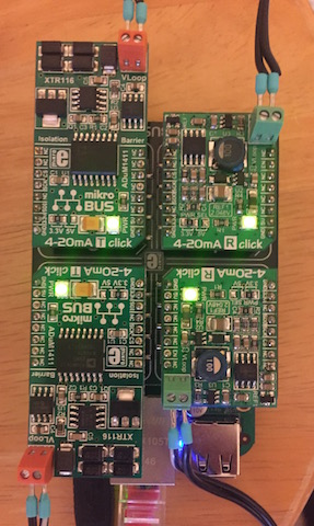
This script was run with a fully populated mikroBUS cape and 4 clickboards! Two 4-20mA transmitters and two 4-20mA receivers. The transmitter in slot 2 is looped to the receiver in slot 1. Likewise, the transmitter in slot 3 is looped to the receiver in slot 4.
Getting the Code
Everything for this tutorial is on the linux-4.3 branch of the BBB-420mA repository. I highly suggest you look at the README and review the instructions there. There are admittedly a lot of moving parts involved here: compiling overlays, adjusting uEnv.txt, understanding SPI and chip select, 4-20mA clickboards, compiling kernel modules, and oh, NodeJS too! Hopefully though when you Google gpio chip select on beaglebone you’ll find your way here and enjoy the read.
With kernel 4.4.14-bone11 i can verify that the DTS overlay works “out of the box”, no kernel patching needed. Probably also works with some earlier kernels, as long as they are newer than the kernel in this article. There is no mention of GPIO chip select on other resources i can find so just wanted to update this for everybody else on the internet looking to do this on their Beaglebone.
Why not just use a quad 2-input OR gate (74HC32) to multiply the /CS pin? No kernel hacking required. Route BBBs /CS to one input of all 4 gates, and 4 GPIOs to the remaining 4 inputs. When the GPIO is high, the output will be high, when the GPIO is low, the output will follow BBBs /CS.
How can i change
spi-cpol;
spi-cpha;
values
In tried to set to all the 4 combination but always the driver reports mode 3
in dts I did
spi-cpol = ;
spi-cpha =;