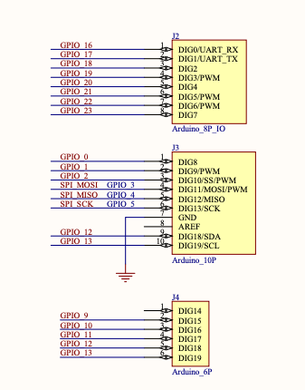
Let’s make use of the HiFive1 Rev B schematics to map out the GPIO controller device pins. Of particular interest is sheet 3, and the following components of the schematic in section D1:
We’re going to use this as our starting point. Three GPIO lines labeled 19, 21, and 22 with LEDs on the lines.
Editor’s Note: This write-up on the SiFive HiFive1 Rev B assumes you have one and are familiar with powering it up, connecting to the serial port, and uploading applications. See our last post if you need to orient yourself with the environment.
Using Metal GPIO
If you haven’t done so already, familiarize yourself with Freedom Metal and the API documentation because we’re going to make use of the GPIO functions.
Recall in the schematic above that the onboard LEDs are tied to GPIO 19 (green LED), GPIO 21 (blue LED), and GPIO 22 (red LED). While the Metal LED API could be used here, we’re going to work directly with the GPIO functions to prove to ourselves that the above GPIO pins are correct, and also check out the 8 color combinations the LED can produce.
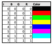
Our basic loop is going to cycle from 0 to 7 and turning on the red LED if bit 1 is set, the green LED if bit 2 is set, and the blue LED if bit 3 is set. This should cause our HiFive1 on-board LED to cycle through the following color chart:
Okay, let’s get the basics down. The GPIO can be accessed by obtaining a struct metal_gpio* using the metal_gpio_get_device function, like this:
|
1 2 3 4 5 6 7 8 |
#include <metal/gpio.h> int main(void) { // Get GPIO device struct metal_gpio* gpio_device = metal_gpio_get_device(0); // do something with the GPIO } |
Now that we have the GPIO device itself, let’s enable GPIO 19 as an output pin. In our schematic take note that the other side of the LED is tied to 3.3V. In other words, there is no setting GPIO 19 high or low required here, if it is enabled you’re going to get the LED on.
To set GPIO 19 as an output:
|
1 |
metal_gpio_enable_output(gpio_device, 19); |
To disable the output of the pin:
|
1 |
metal_gpio_disable_output(gpio_device, 19); |
Now I thinkthis works for the onboard LED because of the way it is wired to the 3.3V supply. In fact, for Metal GPIO pin 19, if you try to write a 1 to it you actually turn off the onboard LED and turn on the header pin 3. Speaking of the header pins…
Arduino Header and Pins
Going back to the board schematic, this time on sheet 3 in sections A5, A6, B5, B6, and C5, C6.
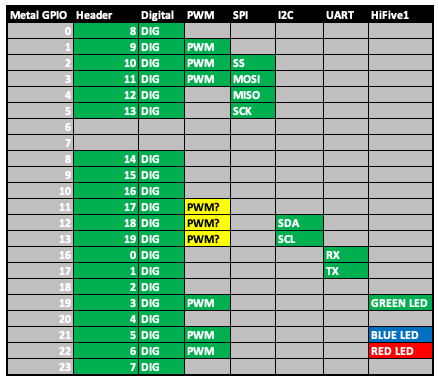
Now this is interesting! Our Arduino headers as well have notes on which GPIOs are digital-only (high or low), those that are PWM-capable, and which pins are shared by SPI, I2C, and UART. All we need to do is put this into a nice table, and the following is (I think) a complete GPIO mapping for the SiFive HiFive1 Rev B board.
For example, if you wanted to start your project with blinking an LED on a breadboard, you might start with one of the “standard” digital input/output pins on the header, say pin 7. The chart above (which is derived from the schematic) shows that pin 7 on the header is tied to pin 23 of the GPIO controller. So to use header pin 7 we might write:
|
1 2 |
metal_gpio_enable_output(gpio_device, 23); metal_gpio_set_pin(gpio_device, 23, 1); |
Or, we could set at the top of our file something along the lines of #define PIN7 23. Just a thought.
Notice once again that this mapping table shows that there are:
- 20 digital pins
- 6 PWM-capable pins
- 1 SPI
- 1 I2C
- 1 UART
Unfortunately SiFive’s HiFive1 Rev B page indicates there are only 19 digital pins and there are 9 PWM-capable ones, so there’s something I’m missing. I think at least for PWM, header pins 17, 18, and 19 on the 6-pin header (to the left of the ESP32) are PWM-capable, though that isn’t clear from the schematic. I’ve asked about that here on the SiFive Forums and will reconcile this post once I learn more.
Getting Some Code
This code is a work in progress and is modeled around the Arduino digital IO library. In digitalio.c you’ll see my take on the functions pinMode and digitalWrite. There is also a delay function to write the ever-popular blinking lights demo. All of this code is MIT licensed with portions copied from the SiFive Freedom E SDK.
Let’s look at how we might use these functions to put the onboard LED through all of the possible colors.
|
1 2 3 4 5 6 7 8 9 10 11 12 13 14 15 16 17 18 19 20 21 22 23 24 25 26 27 28 29 30 31 32 33 34 35 36 37 38 39 40 41 |
#define RED_ON 0x1 #define GREEN_ON 0x2 #define BLUE_ON 0x4 int main(void) { pinMode(METAL_GPIO_19, DISABLE); pinMode(METAL_GPIO_21, DISABLE); pinMode(METAL_GPIO_22, DISABLE); while (1) { for (int i = 0; i < 8; i++) { printf(COLOR_SEQUENCE[i]); if (i & RED_ON) { printf("r "); pinMode(METAL_GPIO_22, OUTPUT); } else { printf("_ "); pinMode(METAL_GPIO_22, DISABLE); } if (i & GREEN_ON) { printf("g "); pinMode(METAL_GPIO_19, OUTPUT); } else { printf("_ "); pinMode(METAL_GPIO_19, DISABLE); } if (i & BLUE_ON) { printf("b\n"); pinMode(METAL_GPIO_21, OUTPUT); } else { printf("_\n"); pinMode(METAL_GPIO_21, DISABLE); } delay(1); } } |
Recall the GPIO pins that map to the on-board LEDs are:
- Red – GPIO_22
- Green – GPIO_19
- Blue – GPIO_21
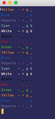
We iterate from 0 to 7 in a loop, test the bits, and set the pins as outputs (since we’re using the onboard LEDs) or disable them. The result is a nice rainbow light show from the HiFive1. If you connect to the serial port you’ll also see the colors being printed out as they are cycled through:
Lagniappe
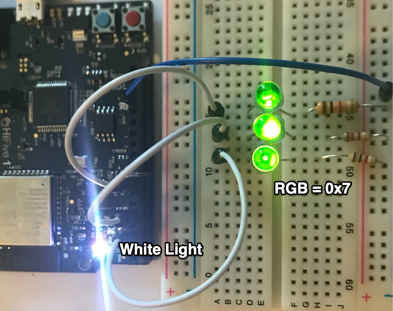
The code that’s actually uploaded to GitHub includes stepping through the binary representation of our LED rainbow and displaying that if you hook up a few LEDs to your breadboard. Check out the code and look closely here at header pins 2, 4, and 7.
Closing Thoughts and What’s Next
Nothing is more fun than working with microcontrollers and embedded systems, and the HiFive1 is no exception. If you take a look at gpios.h in GitHub you can see that I’m looking as to how to best add additional #defines for the various pins. We will see.
